Railroad Spikes: The Backbone Of Track Stability
Last revised: August 29, 2024
By: Adam Burns
Since the industry was founded a railroad spike, or some type of fastening device, has been employed to hold the rails firmly in place to a tie, or some other form of lateral support.
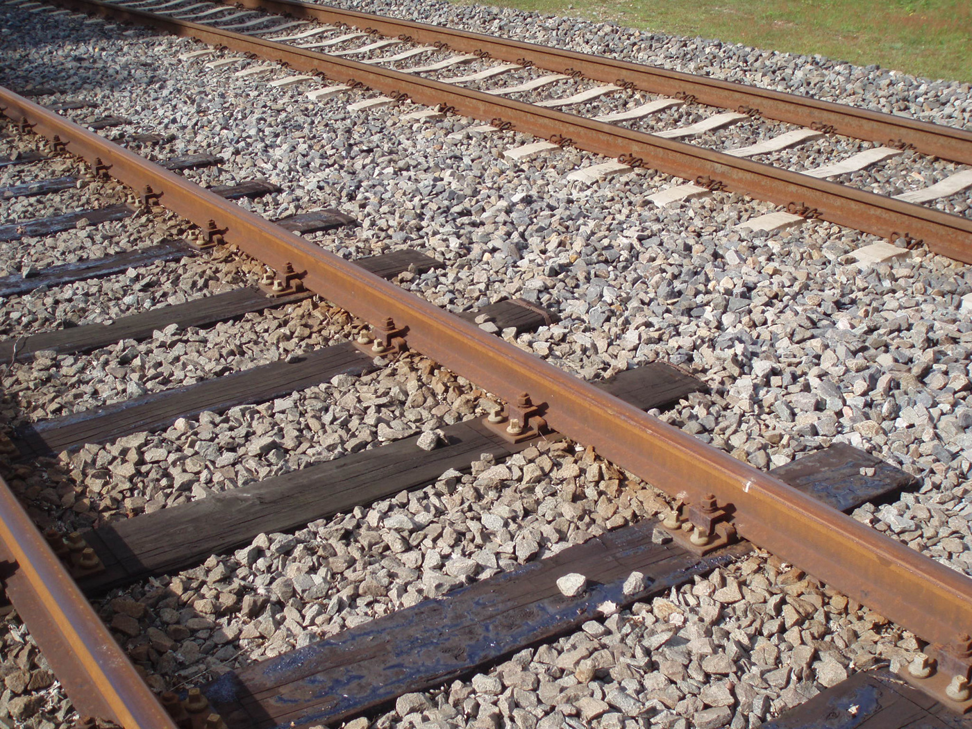
The entire track structure includes the rail, tie, tie-plate, and ballast system all of which have a very important and specific function.
The earliest spikes were simply crude nails and within today's modern industry the most common type has been in regular use since the early 1830s (when used in conjunction with wooden ties).
In addition, following the development of concrete ties specialized clips have become common, which essentially perform the same function but appear nothing like the typical spike.
Photos
History
The spike is one of the most widely recognized pieces of railroad equipment by the general public; whether you work in the industry, enjoy studying it, or even have no interest in trains at all virtually everyone understands what a spike is and its basic function.
During the industry's early years, however, developing today's railroad spike took some time since there was no established practices in regards to either rail fastening systems or much of anything else related to the operation of trains.
The earliest companies such as the Baltimore & Ohio, Camden & Amboy, Mohawk & Hudson, and Delaware & Hudson Canal Company paved the way in setting these future precedents. In particular was the B&O.
Baltimore & Ohio
As our country's first common-carrier the fledgling company's engineers and surveyors often had to guess and use their own intuition regarding how to lay out and construct the right-of-way.
According to the book, Baltimore & Ohio Railroad by Kirk Reynolds and Dave Oroszi, this task fell upon surveryor Lt. Colonel Stephen H. Long of the U.S. Army and chief engineer Jonathan Knight.
They decided upon an easy 0.6 percent ruling grade with a maximum curvature of 14 to 18 degrees. As it turns out, steam locomotives could handle stiffer grades but required easier curves.
Similar issues were encountered in figuring out what materials to use for the track structure and its width. At the time England was the only country producing rolled/solid iron rails.
After testing various techniques from wood and stone to iron straps the B&O decided upon the latter system (thin pieces of iron nailed to wooden blocks) held in place longitudinally with wooden crossties.
In addition, the B&O opted for the English track gauge of 4 feet, 8 1/2 inches. This width proved to be the industry's standard gauge still used today (although it took several decades before it was officially adopted across the industry).
Mounting either strap-iron or solid rails to their wooden or stone crossties also posed a problem. At first, simple nails or pegs were used but this setup proved problematic and unreliable since sometimes these would come loose or simply could not tightly secure the rails to the ties.
In short, a better system was needed and thankfully one was developed at the same time the B&O was still building westward from Baltimore, thanks to Colonel Robert Livingston Stevens.
He conceived a new design that looked like a flattened "I"-beam with a narrow rail-head (the guide-way for the train's wheels) followed by an elongated base for support.
It was a simple but ingenious setup that came to be known as flat bottomed rail but today is commonly known as "T"-rail (flipped upside down it resembles the uppercase letter "T").
Stevens initially ran into problems trying to prove his concept since there were no iron works then in operation within the U.S. So, he sailed to England and had 500 pieces of rail, 15 feet long (weighing 36 pounds per yard) rolled in early 1831.
These would later arrive in Philadelphia that May and placed into service on the Camden & Amboy (the C&A later comprised part of Pennsylvania Railroad's four-track Northeast Corridor, which remains an important artery under Amtrak today), a company which Stevens was president at the time.
It was the first use of "T"-rail in the country and eventually caught on with other railroads.
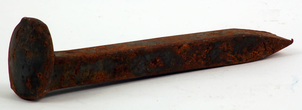
Colonel Stevens also invented a large, hooked nail to hold the rail to the tie via the elongated base. It came to be known as a spike, sometimes referred to as a cut spike or crampon, and was a great improvement over earlier nails or "chairs."
These were often used on early English railways which employed basic "T"-shaped rails without a wide base. A wedge-like device, the chair held the rail to the crosstie/sleeper.
Over the years variations of Stevens' spike have been employed (such as the "dog spike" which utilizes a shortened head with outward facing lugs at the top which aids in the removal process) but essentially, the same basic design has been used for the last two centuries.
When tie plates were introduced around 1900 the spike's effectiveness greatly increased.
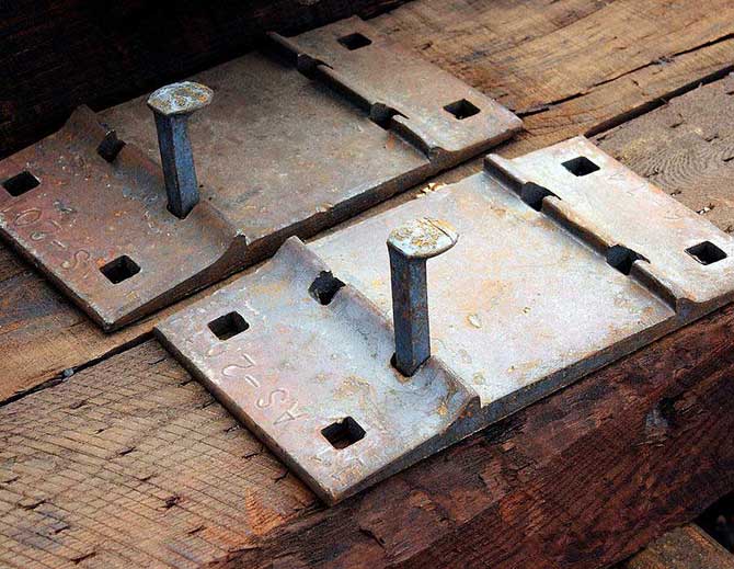
This device, sometimes called a baseplate or sole plate, is constructed of steel and used as part of the track structure when employing wooden crossties; slightly wider (horizontally) on each side the center is flat and smooth in which the rail is housed.
The plate has a very wide horizontal base, usually with four holes on each side for spikes to hold the rail and then fasten everything to the tie.
Once forced into place the plate provides more lateral support and also helps hold the rail to correct gauge.
In the modern age new crossties, such as those made of concrete and composite materials, use a type of clip system and other countries have also used a type of clip even with wooden ties. However, in the U.S. and Canada spikes and tieplates via wooden ties are still the preferred method.
Recent Articles
-
Nevada's - Murder Mystery - Dinner Train Rides
Jan 07, 26 02:12 PM
Seamlessly blending the romance of train travel with the allure of a theatrical whodunit, these excursions promise suspense, delight, and an unforgettable journey through Nevada’s heart. -
West Virginia's - Murder Mystery - Dinner Train Rides
Jan 07, 26 02:08 PM
For those looking to combine the allure of a train ride with an engaging whodunit, the murder mystery dinner trains offer a uniquely thrilling experience. -
Kansas's - Murder Mystery - Dinner Train Rides
Jan 07, 26 01:53 PM
Kansas, known for its sprawling wheat fields and rich history, hides a unique gem that promises both intrigue and culinary delight—murder mystery dinner trains. -
Michigan's - Wine Tasting - Train Rides
Jan 07, 26 12:36 PM
In this article, we’ll delve into the world of Michigan’s wine tasting train experiences that cater to both wine connoisseurs and railway aficionados. -
Indiana's - Wine Tasting - Train Rides
Jan 07, 26 12:33 PM
In this article, we'll delve into the experience of wine tasting trains in Indiana, exploring their routes, services, and the rising popularity of this unique adventure. -
South Dakota's - Wine Tasting - Train Rides
Jan 07, 26 12:30 PM
For wine enthusiasts and adventurers alike, South Dakota introduces a novel way to experience its local viticulture: wine tasting aboard the Black Hills Central Railroad. -
Kentucky Thomas The Train Rides
Jan 07, 26 12:26 PM
If you’ve got a Thomas fan in the house, Day Out With Thomas at the Kentucky Railway Museum is one of those “circle it on the calendar” weekends. -
Michigan's Thomas The Train Rides
Jan 07, 26 12:10 PM
If you’ve got a Thomas fan in the house, few spring outings feel as “storybook-real” as Day Out With Thomas™ at Greenfield Village in Dearborn, Michigan. -
Texas Dinner Train Rides On The TSR!
Jan 07, 26 11:36 AM
Today, TSR markets itself as a round-trip, four-hour, 25-mile journey between Palestine and Rusk—an easy day trip (or date-night centerpiece) with just the right amount of history baked in. -
Iowa Dinner Train Rides In Boone!
Jan 07, 26 11:06 AM
If you’ve ever wished you could pair a leisurely rail journey with a proper sit-down meal—white tablecloths, big windows, and countryside rolling by—the Boone & Scenic Valley Railroad & Museum in Boon… -
Wisconsin Dinner Train Rides In North Freedom!
Jan 06, 26 10:18 PM
Featured here is a practical guide to Mid-Continent’s dining train concept—what the experience is like, the kinds of menus the museum has offered, and what to expect when you book. -
Pennsylvania Dinner Train Rides In Boyertown!
Jan 06, 26 06:48 PM
With beautifully restored vintage equipment, carefully curated menus, and theatrical storytelling woven into each trip, the Colebrookdale Railroad offers far more than a simple meal on rails. -
North Carolina ~ Murder Mystery ~ Dinner Train Ride
Jan 06, 26 11:26 AM
While there are currently no murder mystery dinner trains in the Tarheel State the Burgaw Depot does host a murder mystery dinner experience in September! -
Florida's - Murder Mystery - Dinner Train Rides
Jan 06, 26 11:23 AM
Florida, known for its vibrant culture, dazzling beaches, and thrilling theme parks, also offers a unique blend of mystery and fine dining aboard its murder mystery dinner trains. -
New Mexico's - Wine Tasting - Train Rides
Jan 06, 26 11:19 AM
For oenophiles and adventure seekers alike, wine tasting train rides in New Mexico provide a unique opportunity to explore the region's vineyards in comfort and style. -
Ohio's - Wine Tasting - Train Rides
Jan 06, 26 11:14 AM
Among the intriguing ways to experience Ohio's splendor is aboard the wine tasting trains that journey through some of Ohio's most picturesque vineyards and wineries. -
Connecticut's Thomas The Train Rides
Jan 06, 26 11:06 AM
For 2026, the tour stop at Essex brings Thomas (and Percy, too) to the historic Valley Railroad for a full day of events for the kids. -
Maryland's Thomas The Train Rides
Jan 06, 26 11:00 AM
In 2026, the B&O Railroad Museum in Baltimore welcomes the Let’s Rock, Let’s Roll Tour with four event days that combine a Thomas-themed excursion with other activities. -
Tennessee's Thomas The Train Rides
Jan 06, 26 10:51 AM
Set on the grounds of one of the Southeast’s best-known operating railroad museums, the Thomas the train event blends kid-friendly fun with the unmistakable sights, sounds, and atmosphere of a real wo… -
Georgia's Thomas The Train Rides
Jan 06, 26 10:44 AM
Day Out With Thomas is set to roll back into Cordele in 2026, bringing Thomas the Tank Engine and a full family festival to the SAM Shortline at Georgia Veterans Memorial State Park.


